Lenflex Hose-Professional Hydraulic Hose Fittings Manufacturer Since 2003.
Language
Lenflex Hose-Professional Hydraulic Hose Fittings Manufacturer Since 2003.
LENFLEX - ADAPTER - NPT / JIC / ORFS - 1J / 1J4 / 1J9 / 1JN / 1JN4 / 1JN9 / 1JO / 1JO4 / 1JO9 / 1O / 2F / 2F4 / 2F9 / 2NU / 2NU4 / 2NU9
1J :JIC MALE 74° CONE
1J4 :45° ELBOW JIC MALE 74° CONE
1J9 :90° ELBOW JIC MALE 74° CONE
1JN :JIC MALE 74° CONE / NPT MALE
1JN4 :45° ELBOW JIC MALE 74° CONE / NPT MALE
1JN9 :90° ELBOW JIC MALE 74° CONE / NPT MALE
1JO :JIC MALE 74° CONE / SAE O-RING BOSS L-SERIES ISO 11926-3
1JO4 :45°ELBOW JIC MALE 74° CONE / SAE O-RING BOSS L-SERIES ISO 11926-3
1JO9 :90°ELBOW JIC MALE 74° CONE / SAE O-RING BOSS L-SERIES ISO 11926-3
1O :SAE MALE O-RING BOSS
2F :ORFS MALE O-RING / ORFS FEMALE
2F4 :45° ELBOW ORFS MALE O-RING / ORFS FEMALE
2F9 :90° ELBOW ORFS MALE O-RING / ORFS FEMALE
2NU :NPT MALE / NPSM FEMALE 60° CONE
2NU4 :45° ELBOW NPT MALE / NPSM FEMALE 60° CONE
2NU9 :90° ELBOW NPT MALE / NPSM FEMALE 60° CONE
The JIC male to female adapters, available in NPT, JIC, and ORFS configurations, are expertly designed for seamless connectivity in hydraulic systems. These adapters boast precise dimensions, excellent build quality, and corrosion-resistant materials, ensuring durability and reliability in all applications. With a robust structure and a meticulous production process, these adapters provide a secure and leak-free solution for various fluid transfer needs, making them a crucial component in any hydraulic system.
Team strength is crucial in any project, just like the JIC Male to Female Adapters - NPT / JIC / ORFS excel in creating seamless connections. With a diverse range of sizes and materials, these adapters work in harmony to ensure a secure and efficient transfer of fluids. Their strong, durable construction symbolizes the reliability and expertise of your team, guaranteeing smooth operations and minimal downtime. By incorporating these adapters into your equipment, you demonstrate your team's commitment to quality and precision. Let these adapters be the cornerstone of your team's strength and success in every task at hand.
At JIC, we believe in the strength of teamwork when it comes to creating the best products for our customers. Our Male to Female Adapters are a testament to this belief, designed with precision and quality in mind. The NPT, JIC, and ORFS fittings ensure compatibility and reliability in various applications. Our team of experts works together seamlessly to produce adapters that exceed industry standards and meet the needs of our customers. Trust in the strength of our team to provide you with reliable, high-quality adapters that will ensure a smooth and efficient operation every time.
LENFLEX - ADAPTER - NPT / JIC / ORFS - 1J / 1J4 / 1J9 / 1JN / 1JN4 / 1JN9 / 1JO / 1JO4 / 1JO9 / 1O / 2F / 2F4 / 2F9 / 2NU / 2NU4 / 2NU9
Hydraulic adapter fittings NPT/JIC/ORFS are high-performance components designed for reliable hydraulic connections. These fittings exhibit excellent pressure resistance, typically capable of withstanding pressures up to 6,000 PSI or higher, making them suitable for demanding high-pressure hydraulic applications. They are manufactured from durable materials such as carbon steel, stainless steel, or alloy steel, which provide robustness and resistance to wear and corrosion. This hydraulic hose adapter adhere to stringent international standards like SAE and ISO, ensuring consistent performance and compatibility.
Design & Function
Design Features: Each type has a unique design. NPT adapter uses tapered threads for tight seals, JIC adapter employs a 37° flare for high-pressure sealing, and ORFS adapter uses an O-ring on the flange face for reliable sealing.
Function: To connect hydraulic hoses to various hydraulic components like pumps, cylinders, and valves, ensuring efficient fluid power transmission.
Hydraulic Adapter Fittings Advantages
Durability: Resistant to wear, corrosion, and high pressure.
Reliability: Ensures secure connections and minimal risk of leaks.
Versatility: Suitable for diverse hydraulic systems and applications.
Applications
1.Industrial Use: Applied in industrial machinery, manufacturing equipment, and factory automation systems.
2.Construction & Agriculture: Used in construction machinery like excavators and agricultural equipment like tractors.
Specification:
LENFLEX provides various types of hose adapters, such as NPT adapter, ORFS adapter, JIC adapter etc,. Detailed specifications of thread dimensions, tolerances, and seal types for each fitting standard.
1J :JIC MALE 74° CONE
Technical Parameters:
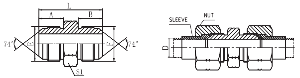
PART NO. | THREAD | DIMENSIONS | ||||
E | F | A | B | L | S1 | |
L1J-02 | 5/16"×24 | 5/16"×24 | 11.4 | 11.4 | 29 | 12 |
L1J-02-03 | 5/16"×24 | 3/8"×24 | 11.4 | 12.2 | 29.5 | 12 |
L1J-03 | 3/8"×24 | 3/8"×24 | 12.2 | 12.2 | 30.5 | 12 |
L1J-04 | 7/16"×20 | 7/16"×20 | 14 | 14 | 34 | 12 |
L1J-04-05 | 7/16"×20 | 1/2"×20 | 14 | 14 | 34 | 14 |
L1J-04-06 | 7/16"×20 | 9/16"×18 | 14 | 14.1 | 34.1 | 17 |
L1J-04-08 | 7/16"×20 | 3/4"×16 | 14 | 16.7 | 38.5 | 22 |
L1J-05 | 1/2"×20 | 1/2"×20 | 14 | 14 | 34 | 14 |
L1J-05-06 | 1/2"×20 | 9/16"×18 | 14 | 14.1 | 34.1 | 17 |
L1J-05-08 | 1/2"×20 | 3/4"×16 | 14 | 16.7 | 38.5 | 22 |
L1J-05-10 | 1/2"×20 | 7/8"×14 | 14 | 19.3 | 41 | 24 |
L1J-06 | 9/16"×18 | 9/16"×18 | 14.1 | 14.1 | 34.2 | 17 |
L1J-06-08 | 9/16"×18 | 3/4"×16 | 14.1 | 16.7 | 38.5 | 22 |
L1J-06-10 | 9/16"×18 | 7/8"×14 | 14.1 | 19.3 | 41.5 | 24 |
L1J-06-12 | 9/16"×18 | 1.1/16"×12 | 14.1 | 21.9 | 46 | 30 |
L1J-08 | 3/4"×16 | 3/4"×16 | 16.7 | 16.7 | 42 | 22 |
L1J-08-10 | 3/4"×16 | 7/8"×14 | 16.7 | 19.3 | 44 | 24 |
L1J-08-12 | 3/4"×16 | 1.1/16"×12 | 16.7 | 21.9 | 48.5 | 30 |
L1J-08-16 | 3/4"×16 | 1.5/16"×12 | 16.7 | 23.1 | 51 | 36 |
L1J-10 | 7/8"×14 | 7/8"×14 | 19.3 | 19.3 | 46.5 | 24 |
L1J-10-12 | 7/8"×14 | 1.1/16"×12 | 19.3 | 21.9 | 51 | 30 |
L1J-10-16 | 7/8"×14 | 1.5/16"×12 | 19.3 | 23.1 | 53.5 | 36 |
L1J-12 | 1.1/16"×12 | 1.1/16"×12 | 21.9 | 21.9 | 54 | 30 |
L1J-12-14 | 1.1/16"×12 | 1.3/16"×12 | 21.9 | 22.6 | 55.5 | 32 |
L1J-12-16 | 1.1/16"×12 | 1.5/16"×12 | 21.9 | 23.1 | 56 | 36 |
L1J-14 | 1.3/16"×12 | 1.3/16"×12 | 22.6 | 22.6 | 56 | 32 |
L1J-14-16 | 1.3/16"×12 | 1.5/16"×12 | 22.6 | 23.1 | 56.5 | 36 |
L1J-16 | 1.5/16"×12 | 1.5/16"×12 | 23.1 | 23.1 | 57 | 36 |
L1J-16-20 | 1.5/16"×12 | 1.5/8"×12 | 23.1 | 24.3 | 60.5 | 46 |
L1J-16-24 | 1.5/16"×12 | 1.7/8"×12 | 23.1 | 27.5 | 65.5 | 50 |
L1J-20 | 1.5/8"×12 | 1.5/8"×12 | 24.3 | 24.3 | 62 | 46 |
L1J-20-24 | 1.5/8"×12 | 1.7/8"×12 | 24.3 | 27.5 | 67 | 50 |
L1J-20-32 | 1.5/8"×12 | 2.1/2"×12 | 24.3 | 33.9 | 75 | 65 |
L1J-24 | 1.7/8"×12 | 1.7/8"×12 | 27.5 | 27.5 | 70 | 50 |
L1J-24-32 | 1.7/8"×12 | 2.1/2"×12 | 27.5 | 33.9 | 78.5 | 65 |
L1J-32 | 2.1/2"×12 | 2.1/2"×12 | 33.9 | 33.9 | 85 | 65 |
Note: Nut and sleeve should be ordered separately. The nut NB200 and sleeve NB500 is suitable for metric tube, the nut NB200 and sleeve NB300 is suitable inch tube. | ||||||
1JN :JIC MALE 74° CONE / NPT MALE
Technical Parameters:
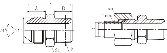
PART NO. | THREAD | DIMENSIONS | ||||
E | F | A | B | L | S1 | |
L1JN-02 | 5/16"×24 | Z1/8"×27 | 11.4 | 10.5 | 28 | 12 |
L1JN-04-02 | 7/16"×20 | Z1/8"×27 | 14 | 10.5 | 30.5 | 12 |
L1JN-04 | 7/16"×20 | Z1/4"×18 | 14 | 15 | 35 | 17 |
L1JN-04-06 | 7/16"×20 | Z3/8"×18 | 14 | 16 | 36 | 19 |
L1JN-04-08 | 7/16"×20 | Z1/2"×14 | 14 | 19.5 | 41.5 | 24 |
L1JN-05-04 | 1/2"×20 | Z1/4"×18 | 14 | 15 | 35 | 17 |
L1JN-05-06 | 1/2"×20 | Z3/8"×18 | 14 | 16 | 36 | 19 |
L1JN-05-08 | 1/2"×20 | Z1/2"×14 | 14 | 19.5 | 41.5 | 24 |
L1JN-06-04 | 9/16"×18 | Z1/4"×18 | 14.1 | 15 | 34.5 | 17 |
L1JN-06 | 9/16"×18 | Z3/8"×18 | 14.1 | 16 | 36 | 19 |
L1JN-06-08 | 9/16"×18 | Z1/2"×14 | 14.1 | 19.5 | 41.5 | 24 |
L1JN-08-04 | 3/4"×16 | Z1/4"×18 | 16.7 | 15 | 39 | 22 |
L1JN-08-06 | 3/4"×16 | Z3/8"×18 | 16.7 | 16 | 40 | 22 |
L1JN-08 | 3/4"×16 | Z1/2"×14 | 16.7 | 19.5 | 44 | 24 |
L1JN-08-12 | 3/4"×16 | Z3/4"×18 | 16.7 | 19.5 | 46.5 | 30 |
L1JN-10-06 | 7/8"×14 | Z3/8"×18 | 19.3 | 16 | 43.5 | 24 |
L1JN-10-08 | 7/8"×14 | Z1/2"×14 | 19.3 | 19.5 | 47 | 24 |
L1JN-10-12 | 7/8"×14 | Z3/4"×14 | 19.3 | 19.5 | 49 | 30 |
L1JN-12-08 | 1.1/16"×12 | Z1/2"×14 | 21.9 | 19.5 | 51 | 30 |
L1JN-12 | 1.1/16"×12 | Z3/4"×14 | 21.9 | 19.5 | 51.5 | 30 |
L1JN-12-16 | 1.1/16"×12 | Z1"×11.5 | 21.9 | 25.5 | 58.5 | 36 |
L1JN-12-20 | 1.1/16"×12 | Z1.1/4"×11.5 | 21.9 | 26.5 | 61.5 | 46 |
L1JN-14-12 | 1.3/16"×12 | Z3/4"×14 | 22.6 | 19.5 | 53 | 32 |
L1JN-16-12 | 1.5/16"×12 | Z3/4"×14 | 23.1 | 19.5 | 53.5 | 36 |
L1JN-16 | 1.5/16"×12 | Z1"×11.5 | 23.1 | 25.5 | 58.5 | 36 |
L1JN-16-20 | 1.5/16"×12 | Z1.1/4"×11.5 | 23.1 | 26.5 | 62.5 | 46 |
L1JN-16-24 | 1.5/16"×12 | Z1.1/2"×11.5 | 23.1 | 27.5 | 65.5 | 50 |
L1JN-20-16 | 1.5/8"×12 | Z1"×11.5 | 24.3 | 25.5 | 63 | 46 |
L1JN-20 | 1.5/8"×12 | Z1.1/4"×11.5 | 24.3 | 26.5 | 63.5 | 46 |
L1JN-20-24 | 1.5/8"×12 | Z1.1/2"×11.5 | 24.3 | 27.5 | 67 | 50 |
L1JN-24-20 | 1.7/8"×12 | Z1.1/4"×11.5 | 27.5 | 26.5 | 69 | 50 |
L1JN-24 | 1.7/8"×12 | Z1.1/2"×11.5 | 27.5 | 27.5 | 70 | 50 |
L1JN-24-32 | 1.7/8"×12 | Z2"×11.5 | 27.5 | 27.5 | 72 | 65 |
L1JN-32 | 2.1/2"×12 | Z2"×11.5 | 33.9 | 27.5 | 78.5 | 65 |
L1JN-32-24 | 2.1/2"×12 | Z1.1/2"×11.5 | 33.9 | 27.5 | 78.5 | 65 |
Note: Nut and sleeve should be ordered separately. The nut NB200 and sleeve NB500 is suitable for metric tube, the nut NB200 and sleeve NB300 is suitable inch tube. | ||||||
1JO :JIC MALE 74° CONE / SAE O-RING BOSS L-SERIES ISO 11926-3
Technical Parameters:
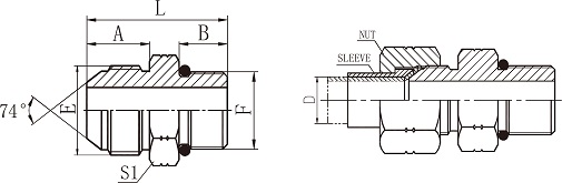
PART NO. | THREAD | O-RING F | DIMENSIONS | ||||
E | F | A | B | L | S1 | ||
L1JO-04-02 | 7/16"×20 | 5/16"×24 | O902 | 14 | 7.5 | 27.5 | 14 |
L1JO-04-03 | 7/16"×20 | 3/8"×24 | O903 | 14 | 7.54 | 27.5 | 14 |
L1JO-04 | 7/16"×20 | 7/16"×20 | O904 | 14 | 9.14 | 29 | 14 |
L1JO-04-05 | 7/16"×20 | 1/2"×20 | O905 | 14 | 9.14 | 29 | 17 |
L1JO-04-06 | 7/16"×20 | 9/16"×I8 | O906 | 14 | 10 | 30 | 17 |
L1JO-04-08 | 7/16"×20 | 3/4"×16 | O908 | 14 | 11.13 | 33 | 22 |
L1JO-05 | 1/2"×20 | 1/2"×20 | O905 | 14 | 9.14 | 29 | 17 |
L1JO-05-04 | 1/2"×20 | 7/16"×20 | O904 | 14 | 9.14 | 29 | 14 |
L1JO-05-06 | 1/2"×20 | 9/16"×I8 | O906 | 14 | 10 | 30 | 17 |
L1JO-05-08 | 1/2"×20 | 3/4"×16 | O908 | 14 | 11.13 | 33 | 22 |
L1JO-06 | 9/16"×18 | 9/16"×18 | O906 | 14.1 | 10 | 30 | 17 |
L1JO-06-04 | 9/16"×18 | 7/16"×20 | O904 | 14.1 | 9.14 | 29 | 17 |
L1JO-06-05 | 9/16"×18 | 1/2"×20 | O905 | 14.1 | 9.14 | 29.5 | 17 |
L1JO-06-08 | 9/16"×18 | 3/4"×16 | O908 | 14.1 | 11.13 | 33 | 22 |
L1JO-06-10 | 9/16"×18 | 7/8"×14 | O910 | 14.1 | 12.7 | 37 | 27 |
L1JO-06-12 | 9/16"×18 | 1.1/16"×12 | O912 | 14.1 | 15.1 | 40 | 32 |
L1JO-08 | 3/4"×16 | 3/4"×16 | O908 | 16.7 | 11.13 | 36 | 22 |
L1JO-08-04 | 3/4"×16 | 7/16"×20 | O904 | 16.7 | 9.14 | 34 | 22 |
L1JO-08-06 | 3/4"×16 | 9/16"×I8 | O906 | 16.7 | 10 | 35 | 22 |
L1JO-08-10 | 3/4"×16 | 7/8"×14 | O910 | 16.7 | 12.7 | 40 | 27 |
L1JO-08-12 | 3/4"×16 | 1.1/16"×12 | O912 | 16.7 | 15.1 | 43 | 32 |
L1JO-08-14 | 3/4"×16 | 1.3/16"×12 | O914 | 16.7 | 15.1 | 43 | 36 |
L1JO-10 | 7/8"×14 | 7/8"×14 | O910 | 19.3 | 12.7 | 42.5 | 27 |
L1JO-10-08 | 7/8"×14 | 3/4"×16 | O908 | 19.3 | 11.13 | 39 | 24 |
L1JO-10-12 | 7/8"×14 | 1.1/16"×12 | O912 | 19.3 | 15.1 | 45.5 | 32 |
L1JO-10-14 | 7/8"×14 | 1.3/16"×12 | O914 | 19.3 | 15.1 | 45.5 | 36 |
L1JO-12 | 1.1/16"×12 | 1.1/16"×12 | O912 | 21.9 | 15.1 | 48 | 32 |
L1JO-12-08 | 1.1/16"×12 | 3/4"×16 | O908 | 21.9 | 11.13 | 43 | 30 |
L1JO-12-10 | 1.1/16"×12 | 7/8"×14 | O910 | 21.9 | 12.7 | 45 | 30 |
L1JO-12-14 | 1.1/16"×12 | 1.3/16"×12 | O914 | 21.9 | 15.1 | 48 | 36 |
L1JO-12-16 | 1.1/16"×12 | 1.5/16"×12 | O916 | 21.9 | 15.1 | 48 | 38 |
L1JO-14 | 1.3/16"×12 | 1.3/16"×12 | O914 | 22.6 | 15.1 | 48.5 | 36 |
L1JO-14-12 | 1.3/16"×12 | 1.1/16"×12 | O912 | 22.6 | 15.1 | 48.5 | 32 |
L1JO-14-16 | 1.3/16"×12 | 1.5/16"×12 | O916 | 22.6 | 15.1 | 50.5 | 38 |
L1JO-16 | 1.5/16"×12 | 1.5/16"×12 | O916 | 23.1 | 15.1 | 49 | 38 |
L1JO-16-12 | 1.5/16"×12 | 1.1/16"×12 | O912 | 23.1 | 15.1 | 49.2 | 36 |
L1JO-16-14 | 1.5/16"×12 | 1.3/16"×12 | O914 | 23.1 | 15.1 | 49 | 36 |
L1JO-16-20 | 1.5/16"×12 | 1.5/8"×12 | O920 | 23.1 | 15.1 | 53 | 50 |
L1JO-20 | 1.5/8"×12 | 1.5/8"×12 | O920 | 24.3 | 15.1 | 54.5 | 50 |
L1JO-20-16 | 1.5/8"×12 | 1.5/16"×12 | O916 | 24.3 | 15.1 | 52.5 | 46 |
L1JO-20-24 | 1.5/8"×12 | 1.7/8"×12 | O924 | 24.3 | 15.1 | 54.5 | 55 |
L1JO-24 | 1.7/8"×12 | 1.7/8"×12 | O924 | 27.5 | 15.1 | 57.5 | 55 |
L1JO-24-20 | 1.7/8"×12 | 1.5/8"×12 | O920 | 27.5 | 15.1 | 57.5 | 50 |
L1JO-24-32 | 1.7/8"×12 | 2.1/2"×11 | O932 | 27.5 | 15.1 | 59.5 | 70 |
L1JO-32 | 2.1/2"×11 | 2.1/2"×11 | O932 | 33.9 | 15.1 | 66 | 70 |
Note: Nut and sleeve should be ordered separately. The nut NB200 and sleeve NB500 is suitable for metric tube, the nut NB200 and sleeve NB300 is suitable inch tube. | |||||||
1O :SAE MALE O-RING BOSS
Technical Parameters:
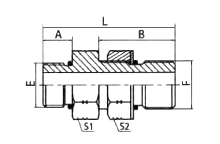
PART NO. | THREAD | O-RING | DIMENSIONS | ||||||
E | F | E | F | A | B | L | S1 | S2 | |
L1O-04OG | 7/16"×20 | 7/16"×20 | O904 | O904 | 9.14 | 18 | 33 | 14 | 17 |
L1O-04-06OG | 7/16"×20 | 9/16"×18 | O904 | O906 | 9.14 | 20 | 35.1 | 17 | 19 |
L1O-06OG | 9/16"×18 | 9/16"×18 | O906 | O906 | 9.93 | 20 | 36 | 17 | 19 |
L1O-06-08OG | 9/16"×18 | 3/4"×16 | O906 | O908 | 9.93 | 22 | 40 | 22 | 24 |
L1O-08OG | 3/4"×16 | 3/4"×16 | O908 | O908 | 11.13 | 22 | 40 | 22 | 24 |
L1O-08-12OG | 3/4"×16 | 1.1/16"×12 | O908 | O912 | 11.13 | 29 | 51 | 32 | 32 |
L1O-10OG | 7/8"×14 | 7/8"×14 | O910 | O910 | 12.7 | 26 | 46 | 27 | 27 |
L1O-12OG | 1.1/16"×12 | 1.1/16"×12 | O912 | O912 | 15.1 | 29 | 54 | 32 | 32 |
L1O-16OG | 1.5/16"×12 | 1.5/16"×12 | O916 | O916 | 15.1 | 29 | 54 | 38 | 41 |
L1O-20OG | 1.5/8"×12 | 1.5/8"×12 | O920 | O920 | 15.1 | 29 | 54 | 50 | 50 |
L1O-24OG | 1.7/8"×12 | 1.7/8"×12 | O924 | O924 | 15.1 | 29 | 54 | 55 | 55 |
2F :ORFS MALE O-RING / ORFS FEMALE
Technical Parameters:
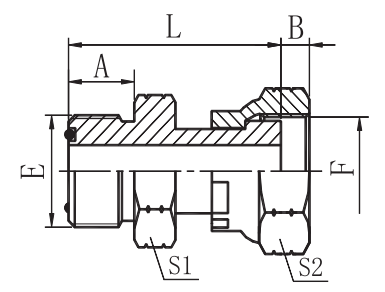
PART NO. | THREAD | O-RING E | DIMENSIONS | |||||
E | F | A | B | L | S1 | S2 | ||
L2F-04 | 9/16"×18 | 9/16"×18 | O011 | 9.8 | 7.5 | 33 | 17 | 19 |
L2F-04-06 | 9/4 6×8 | 11/16"×16 | O011 | 9.8 | 9.5 | 34.5 | 17 | 22 |
L2F-04-08 | 9/16"×18 | 13/16"×16 | O011 | 9.8 | 11.5 | 36.5 | 19 | 27 |
L2F-06-04 | 11/16"×16 | 9/16"×18 | O012 | 11.2 | 7.5 | 35.5 | 19 | 19 |
L2F-06 | 11/16"×16 | 11/16"×16 | O012 | 11.2 | 9.5 | 38.5 | 19 | 22 |
L2F-06-08 | 11/16"×16 | 13/16"×16 | O012 | 11.2 | 11.5 | 37.7 | 19 | 27 |
L2F-06-10 | 11/16"×16 | 1"×14 | O012 | 11.2 | 12.5 | 43.7 | 24 | 32 |
L2F-08-06 | 13/16"×16 | 11/16"×16 | O014 | 12.8 | 9.5 | 41 | 22 | 22 |
L2F-08 | 13/16"×16 | 13/16"×16 | O014 | 12.8 | 11.5 | 43 | 22 | 27 |
L2F-08-10 | 13/16"×16 | 1"×14 | O014 | 12.8 | 12.5 | 45.5 | 24 | 32 |
L2F-08-12 | 13/16"×16 | 1.3/16"×12 | O014 | 12.8 | 13 | 49 | 30 | 36 |
L2F-10-08 | 1"×14 | 13/16"×16 | O016 | 15.5 | 11.5 | 47.5 | 27 | 27 |
L2F-10 | 1"×14 | 1"×14 | O016 | 15.5 | 12.5 | 51.5 | 27 | 32 |
L2F-10-12 | 1"×14 | 1.3/16"×12 | O016 | 15.5 | 13 | 51.5 | 30 | 36 |
L2F-10-16 | 1"×14 | 1.7/16"×12 | O016 | 15.5 | 14 | 56 | 36 | 41 |
L2F-12-08 | 1.3/16"×12 | 13/16"×16 | O018 | 17 | 11.5 | 50.5 | 32 | 27 |
L2F-12-10 | 1.3/16"×12 | 1"×14 | O018 | 17 | 12.5 | 54.5 | 32 | 32 |
L2F-12 | 1.3/16"×12 | 1.3/16"×12 | O018 | 17 | 13 | 56 | 32 | 36 |
L2F-12-16 | 1.3/16"×12 | 1.7/16"×12 | O018 | 17 | 14 | 58 | 36 | 41 |
L2F-16-12 | 1.7/16"×12 | 1.3/16"×12 | O021 | 17.5 | 13 | 58 | 38 | 36 |
L2F-16 | 1.7/16"×12 | 1.7/16"×12 | O021 | 17.5 | 14 | 60 | 38 | 41 |
L2F-16-20 | 1.7/16"×12 | 1.11/16"×12 | O021 | 17.5 | 15 | 58 | 41 | 50 |
L2F-20-16 | 1.11/16"×12 | 1.7/16"×12 | O025 | 17.5 | 14 | 58.5 | 46 | 41 |
L2F-20 | 1.11/16"×12 | 1.11/16"×12 | O025 | 17.5 | 15 | 58 | 46 | 50 |
L2F-20-24 | 1.11/16"×12 | 2"×12 | O025 | 17.5 | 17 | 65.5 | 50 | 60 |
L2F-24-20 | 2"×12 | 1.11/16"×12 | O029 | 17.5 | 15 | 64 | 55 | 50 |
L2F-24 | 2"×12 | 2"×12 | O029 | 17.5 | 17 | 61.5 | 55 | 60 |
2NU :NPT MALE / NPSM FEMALE 60° CONE
Technical Parameters:
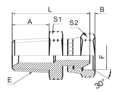
PART NO. | THREAD | DIMENSIONS | |||||
E | F | A | B | L | S1 | S2 | |
L2NU-02 | Z1/8"×27 | 1/8"×27 | 10.5 | 6 | 25.5 | 12 | 15 |
L2NU-02-04 | Z1/8"×27 | 1/4"×18 | 10.5 | 5 | 27.5 | 12 | 19 |
L2NU-04-02 | Z1/4"×18 | 1/8"×27 | 15 | 6 | 30 | 14 | 15 |
L2NU-04 | Z1/4"×18 | 1/4"×18 | 15 | 5 | 32 | 17 | 19 |
L2NU-04-06 | Z1/4"×18 | 3/8"×18 | 15 | 6.5 | 33 | 17 | 22 |
L2NU-04-08 | Z1/4"×18 | 1/2"×14 | 15 | 7.8 | 35 | 19 | 27 |
L2NU-06 | Z3/8"×18 | 3/8"×18 | 16 | 6.5 | 34.5 | 19 | 22 |
L2NU-06-04 | Z3/8"×18 | 1/4"×18 | 16 | 5 | 33 | 19 | 19 |
L2NU-06-08 | Z3/8"×18 | 1/2"×14 | 16 | 7.8 | 36 | 19 | 27 |
L2NU-08 | Z1/2"×14 | 1/2"×14 | 19.5 | 7.8 | 41.5 | 22 | 27 |
L2NU-08-04 | Z1/2"×14 | 1/4"×18 | 19.5 | 5 | 38.5 | 22 | 19 |
L2NU-08-06 | Z1/2"×14 | 3/8"×18 | 19.5 | 6.5 | 39.5 | 22 | 22 |
L2NU-12 | Z3/4"×14 | 3/4"×14 | 19.5 | 10.5 | 44.5 | 30 | 32 |
L2NU-12-06 | Z3/4"×14 | 3/8"×18 | 19.5 | 6.5 | 41.5 | 30 | 22 |
L2NU-12-08 | Z3/4"×14 | 1/2"×14 | 19.5 | 7.8 | 43.5 | 30 | 27 |
L2NU-12-16 | Z3/4"×14 | 1"×11.5 | 19.5 | 11 | 46.5 | 32 | 41 |
L2NU-16-12 | Z1"×11.5 | 3/4"×14 | 25.5 | 10.5 | 51.5 | 36 | 32 |
L2NU-16 | Z1"×11.5 | 1"×11.5 | 25.5 | 11 | 52.5 | 36 | 41 |
L2NU-16-20 | Z1"×11.5 | 1.1/4"×11.5 | 25.5 | 11.5 | 58.5 | 41 | 50 |
L2NU-20-16 | Z1.1/4"×11.5 | 1"×11.5 | 26.5 | 11 | 57.5 | 46 | 41 |
L2NU-20 | Z1.1/4"×11.5 | 1.1/4"×11.5 | 26.5 | 11.5 | 59.5 | 46 | 50 |
L2NU-20-24 | Z1.1/4"×11.5 | 1.1/2"×11.5 | 26.5 | 12.5 | 59.5 | 46 | 55 |
L2NU-24-20 | Z1.1/2"×11.5 | 1.1/4"×11.5 | 27.5 | 11.5 | 62.5 | 50 | 50 |
L2NU-24 | Z1.1/2"×11.5 | 1.1/2"×11.5 | 27.5 | 12.5 | 62.5 | 50 | 55 |
L2NU-32 | Z2"×11.5 | 2"×11.5 | 27.5 | 16 | 64.5 | 65 | 70 |
Production process:
1.Cut the raw materials (steel) into suitable blanks by sawing machine according to the production demand.
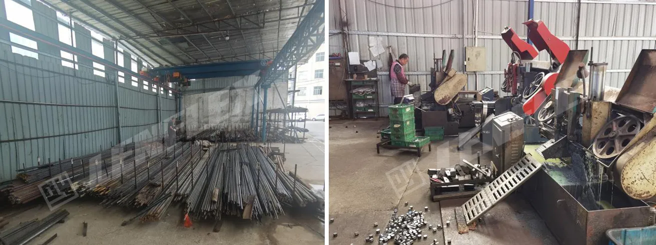
2.CNC machining, machining according to the drawing requirements.
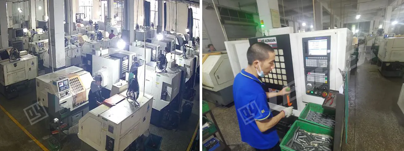
3.Drilling processing, drilling as required.
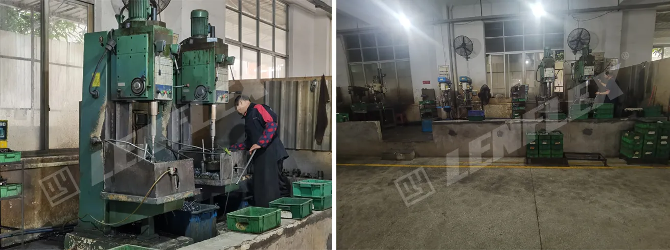
4. Completion inspection. Inspect the processed products.
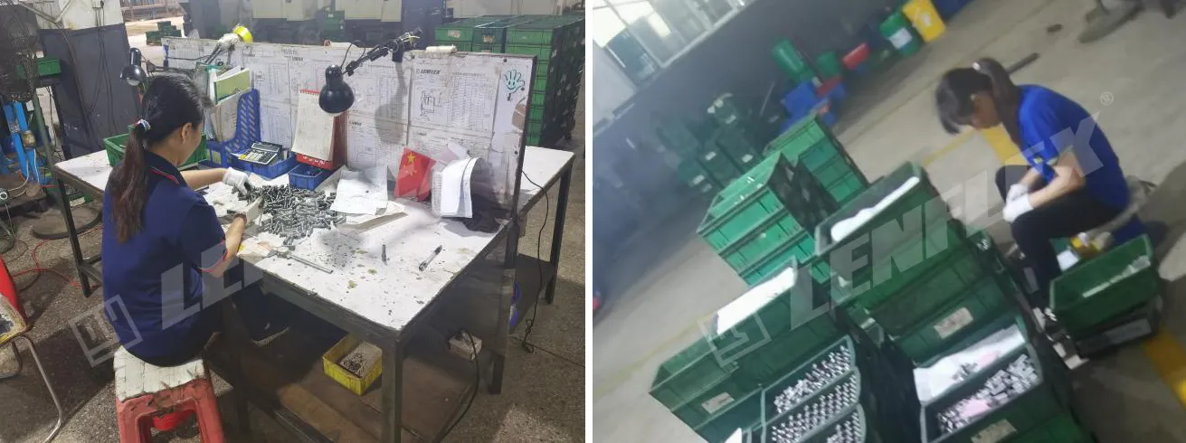
5. External plating, surface treatment.
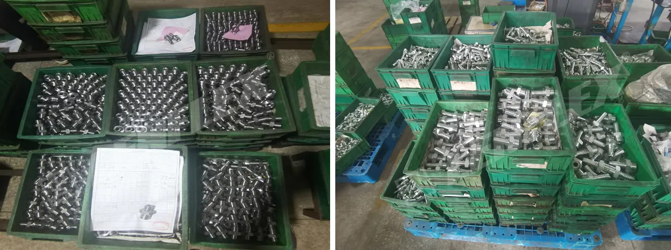
Before electroplating After electroplating
6. Product assembly: assemble the products to be assembled.
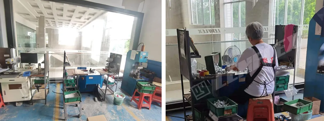
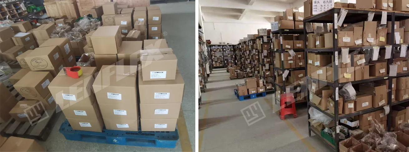
7. Product warehousing and preparation.

ONE-STOP SOLUTION OF HYDRAULIC COMPONENTS.

